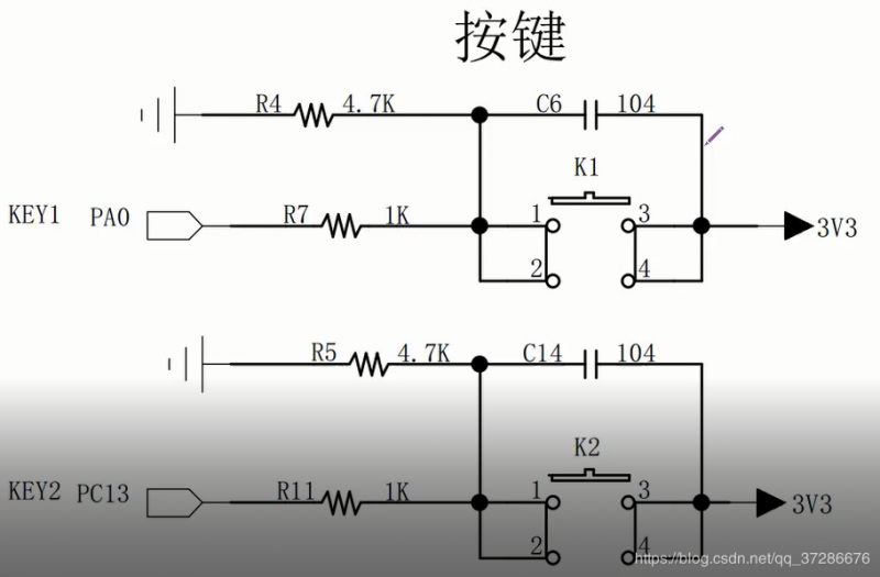
按鍵硬件電路:

分析電路:按鍵K1按下,接通高電平3.3V,為了保護(hù)GPIO,加了限流電阻(R7),沒按下的時(shí)候是接地的,上升沿輸入。
PA0具有自動喚醒的功能(必須上升沿才能喚醒),電容C6用以硬件消抖(電容不斷充放電),這樣軟件就不用延時(shí)來消抖,
K2電路同。
GPIO輸入:GPIO數(shù)據(jù)輸入寄存器IDR,只要讀取這個(gè)寄存器就可以。
bsp_key.c 按鍵初始化:
#include “bsp_key.h”
void KEY_GPIO_Config(void)
{
GPIO_InitTypeDef? GPIO_InitStruct;
RCC_APB2PeriphClockCmd(KEY1_GPIO_CLK, ENABLE);
RCC_APB2PeriphClockCmd(KEY2_GPIO_CLK, ENABLE);
GPIO_InitStruct.GPIO_Pin = KEY1_GPIO_PIN;
GPIO_InitStruct.GPIO_Mode = GPIO_Mode_IN_FLOATING;
GPIO_Init(KEY1_GPIO_PORT, &GPIO_InitStruct);
GPIO_InitStruct.GPIO_Mode = GPIO_Mode_IN_FLOATING;
GPIO_Init(KEY2_GPIO_PORT, &GPIO_InitStruct);
}
uint8_t Key_Scan(GPIO_TypeDef *GPIOx,uint16_t GPIO_Pin)
{
if( GPIO_ReadInputDataBit(GPIOx, GPIO_Pin) == KEY_ON )
{
// ?éê??ì2a
while( GPIO_ReadInputDataBit(GPIOx, GPIO_Pin) == KEY_ON );
return KEY_ON;
}
else return KEY_OFF;
}
bsp_key.h
#ifndef __BSP_KEY_H
#define __BSP_KEY_H
#include “stm32f10x.h”
#define? KEY_ON? ? ? 1
#define? KEY_OFF? ? ?0
#define KEY1_GPIO_PIN? ? ? ? ? ? ? GPIO_Pin_0
#define KEY1_GPIO_PORT? ? ? ? ? ? ?GPIOA
#define KEY1_GPIO_CLK? ? ? ? ? ? ? RCC_APB2Periph_GPIOA
#define KEY2_GPIO_PIN? ? ? ? ? ? ? GPIO_Pin_13
#define KEY2_GPIO_PORT? ? ? ? ? ? ?GPIOC
#define KEY2_GPIO_CLK? ? ? ? ? ? ? RCC_APB2Periph_GPIOC
void KEY_GPIO_Config(void);
uint8_t Key_Scan(GPIO_TypeDef *GPIOx,uint16_t GPIO_Pin);
#endif /* __BSP_KEY_H */
main.c
#include “stm32f10x.h”? ?//
#include “bsp_led.h”
#include “bsp_key.h”
void Delay( uint32_t count )
{
for(; count!=0; count–);
}
int main(void)
{
LED_GPIO_Config();
KEY_GPIO_Config();
while(1)
{
if( Key_Scan(KEY1_GPIO_PORT,KEY1_GPIO_PIN) ==KEY_ON )
LED_G(1)
if( Key_Scan(KEY2_GPIO_PORT,KEY2_GPIO_PIN) ==KEY_ON )
LED_G(0)
// if
}
}
led_bsp.c與led_bsp.h參考上一篇使用庫函數(shù)點(diǎn)亮LED。
以此我們能夠通過這個(gè)程序檢測按鈕是否按下,并將值輸入到對應(yīng)PORT,保存在GPIO數(shù)據(jù)輸入寄存器IDR中。


